Introducing the world’s first tube-based data clocking device: the SuperTubeClock™
By incorporating a low-noise mini-triode vacuum tube into the digital clock, this boldly conceived design provides vastly superior resolution, detail retrieval, improved clarity, increased definition and detail from top to bottom.

AC OFFSET KILLER
AC Offset Killer is about goose bumps. The ones you get when music comes out of a background so quiet, you may say to yourself “Just how is this possible?” PrimaLuna custom-winds our own massive toroidal power transformers that are low in hum and EMI. But we wanted more. Our engineers designed the AC Offset Killer to lower transformer noise to a place no other manufacturer dreams of going, regardless of how bad your electricity is. The result? Sense of space. Texture. The resonance of an acoustic guitar or violin string that seems to trail on forever. The AC Offset Killer will amaze you.
PREMIUM PARTS
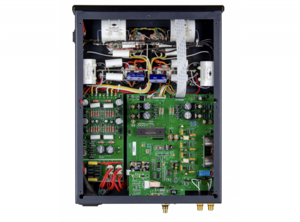
Premium parts including polypropylene coupling caps, triple pi power supply filters, custom designed isolation transformers which separate the analog and digital devices, resulting in decreased signal degradation and improved sonics from top to bottom. Many DACs weigh in at ten pounds or less. The EVO 100 Tube DAC weighs nearly 29 pounds!
POINT TO POINT WIRING
You spend a lot of money on interconnects. So why have the signal go right from the RCA jacks or speaker terminals into circuit boards with copper traces so thin you can hardly see them? What’s high-end about that?
PrimaLuna employs Point to Point Wiring on all products. The entire signal path, including resistors and capacitors, is painstakingly hand wired with heavy-gauge cable by craftsman.
DUAL MONO TOPOLOGY
Per channel dedicated tubes. While it is fine to use a single tube as a buffer for both channels and claim your DAC is “tube”, it can’t be compared to the PrimaLuna design and what it does for the music.

VACUUM TUBE RECTIFIED
Vacuum tube rectified power supply incorporates eleven separate power supply regulation circuits. Tube rectification is synonymous with organic sound, especially when compared to DACs being known as sounding like “a computer”.
USB DIGITAL INPUT
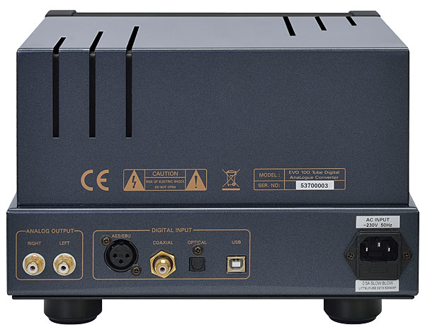
USB digital input allows using your computer for storage and playback of your music with all the benefits of features like playlists and easier access to your whole music library. Rather than just add in an USB input as an afterthought, PrimaLuna engineers searched endlessly looking for the best-sounding USB interface we could find. Our USB input converts the jitter-filled USB digital signal to S/PDIF, dramatically improving the digital signal quality before it gets to the SuperTubeClock. This USB input is a true high-resolution digital input.
The SuperTubeClock™
This is where the magic happens… the SuperTubeClock™ replaces the solid state oscillator normally found in a DAC with a mini triode vacuum tube. By using a tube, we have significantly lowered the amount of jitter and noise, resulting in superior detail retrieval. This in turn yields superior detail and dynamics from top to bottom, and improved overall musicality.
First a note on the tube itself: The tube is a very rugged, long-life Russian military Triode specifically designed for oscillation purposes… which is its function here. It is running very conservatively so life expectancy is roughly 5 to 10 years of operating time. The small glass envelope guarantees very low microphonics.
Triode tubes are inherently low noise devices, and extremely linear when used properly. This means that the oscillation frequency wave it produces is very pure and clean. The noise in the sidebands, from 10Hz to 100kHz on either side of the oscillation frequency, is extremely low. This is the important spectrum for audio. Everything below and beyond that can be ignored.
When you reclock the inputs, any noise that is generated here appears unfiltered and unattenuated at the input of the conversion chip, and injects jitter, which from then on is an indistinguishable part of the digital audio stream. No amount of cleaning will ever be able to remove this noise once it reaches this point; it has become part of the audio signal. This noise “rides” on the audio signal, so you do not hear it as noise, but as smearing of notes and masking of detail. There is a distinctive loss of dynamics, tonal purity, inter-transient silence, and sense of timing. We call this “noise modulation.”
This is why the low noise, especially in the 10Hz-100kHz sidebands of the oscillator, is so crucial. Again: below and beyond these frequency extremes is trivial, because it will not affect the audio, and will not reach the analog outputs.
When the clock is used to clock the DAC chip, a similar situation occurs as described above: the noise appears at the location where the digital audio stream is converted to successive steps in a staircase wave, which represents the analog audio signal. Each step has to be EXACTLY 1/441000th, 1/96000th, 1/176400th, or 1/192000th. The injected noise introduces a deviation in time which is the exact replica of that noise. This means that the audio signal at the outputs of the DAC chip has the noise riding on it, again as an inherent part of the signal. No amount of filtering will remove the noise once it reaches this step. Again we experience that smear and detail masking, with that distinctive loss of dynamics, tonal purity, inter-transient silence, and sense of timing. Here you see how much sense it makes to reclock BOTH the inputs AND the DAC chip.
The oscillation frequency wave a tube produces is a sine wave. That’s no good: It has to be converted to a square wave. This is a very delicate procedure: when the rising and falling edges of a square wave are not steep enough, there exists a certain window during which the actual transition of the data bit is not exactly time-defined. It leaves room to be either too late or too early. This is a partly random process, and partly dependent on surrounding conditions; such as power supply voltage variations, ground noise, inherent CMOS or chip crosstalk in the decoder or DAC chip, etc. All these timing variations are noise, and are called jitter from various sources. The steeper the edges, the more exactly defined the transition moment will be, resulting in less noise (jitter). When a clock produces a very stable frequency with such low jitter, there will be a more accurate reproduction of the original analog waveform of the music.
Here are a few real SuperTubeClock™ pictures of what it can do: experts will certainly like them. No other commercial clock on earth will produce a square wave as this one.
Each square wave seen below is measured on a Philips PM3295A analog 400MHz oscilloscope using LeCroy 10:1 probes. These probes attenuate the signal by a factor of 10, in order to not load the device under test with any load, resistive or capacitive. So the vertical resolution on the scope image has to be multiplied by 10. For instance when you see ~0.1V, then it is in reality measuring ~1V(AC).
The SuperTubeClock™ generating a square wave at 8.4672mHz. The vertical slope is measured at ~500mV (each black horizontal line represents 500mV counting from top to bottom). The vertical peak-to-peak travel of the square wave at this frequency is 3.5 Volts, which is excellent.
Each black vertical line going from left to right represents 10 nanoseconds. The faster a clock can go from peak to peak, the better.
Square waves present themselves more and more like sine waves the higher you go in frequency. So an 8.4672mHz wave like the one above is still identifiable as a square wave, but as we approach 42.2mHz, typically a square wave will be almost fully rounded off and appear as a sine wave. As a square wave begins to round off, it means the timing of the digital transmissions has become more insecure, allowing for the introduction of more noise and jitter that is then presented to the DAC.
Here we see the square wave generated by the SuperTubeClock™ at 42.2mHz. As you can see, the square wave still has a very discernible square shape. This means the clock is VERY fast, leaving very little time to introduce jitter and noise which can interfere with sound quality as mentioned above. Look closely at the image on the left (click to enlarge). Each black vertical line running from left to right represents 5 nanoseconds. The time it takes the slope to go from the top bar to the bottom takes up roughly 1/3 of that black square, which is about 1.67 nanoseconds.
Think about it.. that’s 1.6 BILLIONTHS of a second. Each black horizontal line in this measurement represent ~1V from top to bottom. Just as in the first wave above, the peak-to-peak travel at 42.2mHz is about 3.6 Volts, which again is excellent.
This kind of speed is crucial to ensure accuracy in detail retrieval. This in turn introduces less noise and jitter, resulting in better transients, increased clarity, improved dynamics, and a pure, musical tonality.


